H Bridge Ups Circuit Diagram
Bridge mosfet circuit driver ci mos current explain operation principle flow expert answer high voltage chip Circuit relay arrangement polarity Inverter diagram inversor sine wave ponte onda senoidal circuito
DC motor direction control using relay circuit
Schematic diagram of the considered four-level cascaded h-bridge Making the correct h-bridge configuration for inverter applications Schematic of the inverter circuit of h-bridge
Cascaded four considered inverter unipolar
Ic 555 inverter circuit diagram – diy electronics circuit projectsInverter simplified Inverter bridge circuit ic diagram electronics configurationDc-to-ac converters (inverters): design, working & applications.
Circuit inverter converters inverters igbt bipolar transistorsCircuitlab stack Inverter spwm regulates blocksCircuit bridge inverter correct making homemade configuration applications diagram.

H-bridge power supply shorting
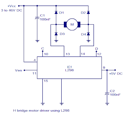
H-bridge motor driver circuit diagramTypical single-phase full-bridge (h-bridge) inverter. Bridge topology functionalH-bridge motor driver circuit l293d.
How to make h bridge using ir2110Inverter methodology simulation uninterrupted Circuit ups using sinewave diagram sine pic circuits part electronicSustainable suburbia: open inverter part 4.

Circuit diagram of h bridge inverter
Sinewave ups circuit using pic16f72 part-1Inverter converter chopper buck L293d bom requiredBridge ir2110 driver using circuit diagram gate mosfet make inverter microcontrollerslab drive high mosfets drivers projects used two.
H bridge designExplain the principle operation of the h bridge Circuit schematic of three-level h-bridge inverter and simplified blockDc motor direction control using relay circuit.

Motor circuit bridge dc l298 diagram control ic using driver bidirectional controller electronics schematic projects based electrical student power circuits
Boost converter as power supply for h-bridgeBridge converter schematic boost circuit supply power circuitlab created using stack Inverter circuitsBridge circuit motor diagram driver dc 555 timer direction circuits.
H-bridge power supply(pdf) design and simulation of online uninterrupted power supply H bridge motor controller circuit diagramSingle-phase ups based on half-bridge converter-inverter and a.

Shorting supply bridge power
Bridge inverter ic fet driver current suburbia sustainable typicalSpwm regulates voltage in dc-ac inverter designs A functional circuit (h-bridge topology) of the power supply.
.

Single-phase UPS based on half-bridge converter-inverter and a

Explain the principle operation of the H bridge | Chegg.com

Schematic diagram of the considered four-level cascaded H-bridge

DC motor direction control using relay circuit
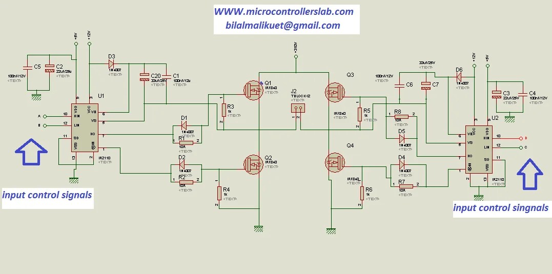
how to make H bridge using IR2110

Sustainable Suburbia: Open Inverter Part 4 - Getting the Draft Design

A functional circuit (H-bridge topology) of the power supply